MR06-200 Hand-held Wire Crimp Pull Sensor
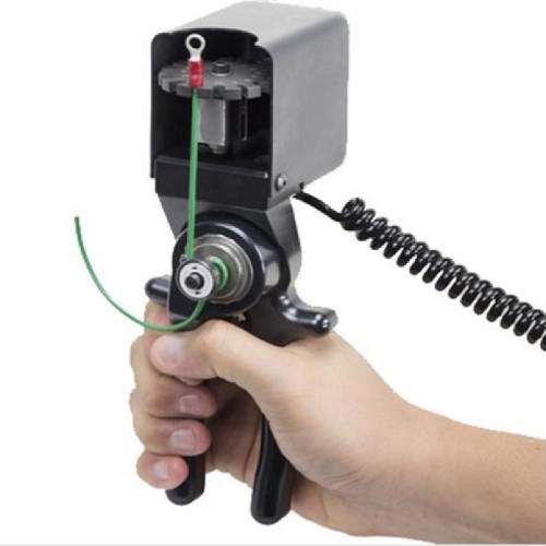
The MR06-200 Wire Crimp Pull Tester is a force sensor designed to make manual field pull testing of crimped wire terminals easy.
This sensor supports a rotary turret with slots for wires from 0,8 mm till 6,4 mm and a load capacity up to 1000 N / 100 KG. The ratcheting mechanism makes it easy to apply up to 1000 N pulling force on the sample.
This force sensor is connected to a Mark-10 Indicator by a Plug & Test® sensor. One of the unique features of the Plug & Test® sensors is that they have their own PCB which stores the calibration and configuration data.
A Plug & Test® sensor can be switched to a different Indicator without the need for calibration or re-configuration.
Once connected and calibrated the MR06-200 is set by rotating the upper grip to an appropriately sized slot (sizes from 0,8mm to 6,3mm) and press the cam shaft button located in the tensioning mechanism. Insert the end of the wire sample in the hole located in the cam shaft. After releasing the cam shaft button the wire is wrapped at least one full rotation clockwise around the cam shaft after which the terminal is inserted in the slot. The sensor is now ready to start testing.
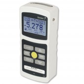
As the MR06-200 is a sensor that needs to be connected to a Series-7i, Series-5i or Series-3i indicator(not included) to display the measured force values.
We are happy to assist you in finding the most suitable configuration for your needs. Please contact us for more information.
Features
- Ergonomic handles and convenient tensioning mechanism
- Member of the Plug & Test® family of interchangeable sensors and indicators
- Compatible with the Series 7i, 5i and 3i digital indicators
- Measures pull forces
- NIST-traceable certificate of calibration with data is included. If the sensor is ordered with an indicator, a certificate for the set (indicator + sensor) can be supplied upon request, at no additional charge.
- Warranty: 3 years
| Model | N | kN | kgF | ozF | lbF |
|---|---|---|---|---|---|
| MR06-200 | 1000 x 0,5 | 1 x 0,0005 | 100 x 0,05 | 3200 x 2 | 200 x 0.1 |
| Model | N | kgF | lbF |
|---|---|---|---|
| MR06-200 | 1000 x 1 | 100 x 0,1 | 200 x 0.2 |
General information
Mark-10 M7I, M5I, and M3I indicators are used in combination with Plug & Test® sensors and can therefore accommodate numerous force and torque measurement requirements, from 1 N to 50 kN (0.25 to 10,000 lbF) of force, and from 7 Ncm to 550 Nm (10 ozFin to 5,000 lbFin) of torque.
Plug & Test® sensors can be used handheld or mounted to a fixture or test stand for more accurate and repeatable testing results.
The sensors are separately calibrated therefore they can be disconnected from one indicator and connected to another without the need for re-calibration or re-configuration as this is stored in the PCB located inside the smart connector.
Accuracy
System accuracy is determined by the combination of Indicator and sensor combined. To determine the total system accuracy the accuracy value of the sensor is added to the value of the indicator.
As the Indicators have different accuracy values the total system accuracy may vary between the different indicator/sensor combinations. Indicator Model Accuracy M7I / M5I ±0,1% of full scale M3I ±0,2% of full scale.
Example 1 Model MR01-100 sensor with Model M5I Indicator MR01-100 ±0,15% of full scale + M5I ±0,1% of full scale = Total ±0,25% of full scale This translates into a fixed error of up to: 0,25% x 500 N = 1,25 N
Example 2 Model MR50-50Z sensor with Model M3I Indicator MR50-50Z ±0,35% of full scale + M3I ±0,2% of full scale = Total ±0,55% of full scale This translates into a fixed error of up to: 0,55% x 50 Ncm = 0,275 Ncm
Because accuracy is defined as a percentage of full scale, the fixed error is possible anywhere on the scale from 0 to the capacity. As such, this value represents an increasingly large error as percentage of reading towards the low end of the scale. It is, therefore, recommended that a sensor is selected with capacity as close as possible to the expected load. The resolution may be different for some sensors depending on whether a M7I, M5I, or M3I indicator is being used. For example, a Series R01 force sensor will display finer resolution when connected to a M5I indicator than when connected to a M3I indicator.
Dimensions
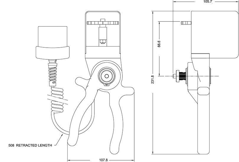
MR06-200 force sensor dimensions.
All dimensions are noted in Inches with metric sizes in [mm] behind.
Related Products
WT3-201E Wire Crimp Pull Tester
- Measures real-time and peak force values
- Ergonomic lever operation produces 1.000 N
- USB, RS-232, Mitutoyo (Digimatic), and analog outputs
More details
WT3-201ME Motorized Wire Pull Tester
- Auto-start upon sample insertion
- Auto-reverse at sample break or load
- Date / time stamp for all saved data (optional function)
More details
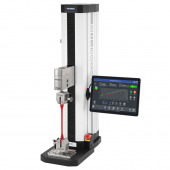
Test stand with IntelliMESUR® F105 / F305 / F505 / F505H
- Integrated Force Sensor: Provides a cable-free interface for the FS05 force sensor.
- Integrated Touchscreen Control Panel: For setting up, running, and analysing data via the IntelliMESUR® control panel.
- Integrated Motion Control and Data Collection: The Plug & Test® system allows seamless use of third-party load cells via the PTAF adapter.
More details
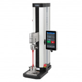
Test Stand with EasyMESUR® F105 / F305 / F505 / F505H
- Integrated Force Sensor: Seamless interface for the FS05 force sensor without cables.
- Integrated Touchscreen Control Panel: For setting up, running, and analysing data via the Easy MESUR® software.
- Test Creation Wizards: Guides that assist the user throughout the configuration process.
More details
Accessories
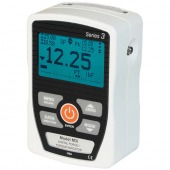
Model-3I Force/Torque Indicator
- Interchangeable force and torque sensors through Plug & Test® technology (sensors are sold separately)
- High-speed 2.000 Hz sampling rate
- Large backlit graphic display
More details
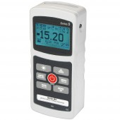
Model-5I Advanced Digital Force/Torque Indicator
- Interchangeable force and torque sensors through, separately sold, Plug & Test® technology
- Password protection for individual keys and calibration
- Sensor password protection, for preventing use of an unauthorized sensor
More details
Model-7i Advanced Force/Torque Indicator
- Interchangeable force and torque sensors through Plug & Test® technology (sensors are sold separately)
- Sensor password protection, for preventing use of an unauthorized sensor
- Password protection for individual keys and calibration
More details
Specifications
| Accuracy | ±0.5% of full scale |
| Safe overload | 150% of full scale ( Indicator display shows “OVER” at 110% and above) |
| Operating temperature | 4 to 38° C |
| Minimum Sample length | 180 mm, excluding termination |
| Wire gauge range | AWG 20 - AWG 3 (0,8 - 6,4 mm) |
| Slot widths standard fixture | 0,8 - 1,3 - 1,5 - 2,0 - 2,3 - 2,8 - 3,3- 3,6 - 4,1 - 4,3 - 4,8 - 5,1 - 5,6 - 6,1 - 6,4 mm |
| Weight | 1,2 Kg |
| Warranty | 3 years |
Buy Now
Availability: Available: 1 - 3 days, Delivery time: 1 - 3 weeks, special order request

